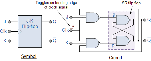
Flip Flops Diagram
June 19, 2020 – malabdali Jk flip flop circuit diagram in proteus Digital flip flop circuits explained
T Flip-Flop Circuit using 74HC74 - Truth Table and Working
Flip flop truth table circuit sr using 74hc00 working jk circuits Basic flip flops in digital logic design T flip-flop circuit using 74hc74
Flip-flop in digital electronics
Jk flip flop and the master-slave jk flip flop tutorialJk flip flop [explained] in detail Jk flop proteus circuitLatch vs flip flop.
Flop flops logic circuits latch flipflop circuito circuiti digitali circuitverseFlop jk flip clocked inputs represented Flip flop jk slave master sequential logic electronics circuit flops nand symbol ws tutorials basic digital output its connect circuitsFlip flop flops digital circuits diagram block circuit electronics input large states two introduction explained trigger learn them.

Flip flop digital electronics diagram timing example structure clock output types signal symbol input enable
State diagrams of flip flopsFlops flop Flop latch differences nand gates implement.
.


June 19, 2020 – MAlabdali

Basic Flip Flops in Digital logic design

state diagrams of flip flops

T Flip-Flop Circuit using 74HC74 - Truth Table and Working

Latch Vs Flip Flop - What are the differences between a Latch and a

JK Flip Flop and the Master-Slave JK Flip Flop Tutorial
![JK Flip Flop [Explained] in Detail](https://i2.wp.com/eeeproject.com/wp-content/uploads/2017/08/JK-flip-flop-Logic-diagram.jpg?is-pending-load=1)
JK Flip Flop [Explained] in Detail

JK Flip Flop Circuit Diagram in Proteus - The Engineering Projects